Skip to Content
SIL3X
  • Work with us
    • Our skills
    • Support services
    • Trainings
  • Our activities
    • Nuclear
    • Datacentres
    • Industry
  • News
    • Articles
    • Blogs
  • About us
    • The team
    • Contact us
    • Join us
    • Terms and Conditions
  • English (UK) Français
  • Sign in
SIL3X
      • Work with us
        • Our skills
        • Support services
        • Trainings
      • Our activities
        • Nuclear
        • Datacentres
        • Industry
      • News
        • Articles
        • Blogs
      • About us
        • The team
        • Contact us
        • Join us
        • Terms and Conditions
    • English (UK) Français
    • Sign in

    Studies and sizing of cooling systems

    Size and optimise cooling systems by quantifying their performance and margins under all operating conditions.

    Contact us

    Our types of studies

    Dynamic studies and architecture choices

    Analyse the behaviour of cooling systems over time to size backup capacities and compare architectures.

    Sizing at a steady operating point is not always sufficient to characterise the performance of a cooling system. During equipment loss or a change in configuration, temperatures, flow rates, and powers evolve over time. We conduct dynamic studies to quantify these transients and determine, for example, the time available after the loss of a chiller before the temperature of a buffer tank or circuit exceeds a given criterion.

    These models also allow for the analysis of equipment cycling phenomena. By representing the equipment, their controls, and their consumers, we can identify the conditions likely to cause repeated starts and stops, both on air conditioning systems and on the cooling circuits of backup generators.
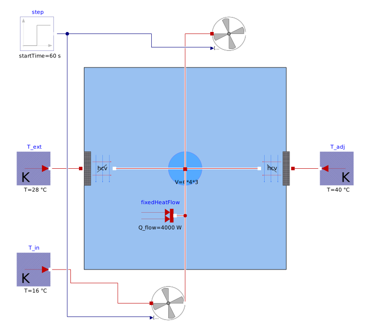
    Dynamic simulation finally constitutes a tool to aid in architectural choice. Different solutions can be compared under conditions representative of their operation, for example to assess the benefits of free cooling or free chilling in a data centre. Energy performance, achieved temperatures, response times, and available margins can thus be compared before finalising design choices.

    For these studies, we use the modelling language Modelica, suitable for representing complex thermo-fluid systems and coupling their various components. SIL3X also contributes to the OpenModelica consortium and develops its own model libraries to meet the specific needs of nuclear ventilation studies.

    Our article on the difference between free cooling and free chilling

    Sizing of hydraulic networks and pumps

    Determine the operating points and balancing of a network before finalising equipment controls.

    A cooling network rarely operates in a single configuration. The isolation of a branch, partial operation of consumers, or switching to a backup unit alters the distribution of flows and pressure losses. A pump selected solely on the nominal point may then operate far from its optimal efficiency, or prove unable to provide the required flow in a degraded configuration.

    We carry out hydraulic modelling of networks by integrating the geometric characteristics of circuits, singularities, heat exchangers, and control devices. Supplier data — flow/pressure curves, efficiency, NPSH, speed variation range — are integrated into the models to represent the actual behaviour of the equipment.


    These models allow for checking the balance of the network in each configuration, quantifying the available margins, and defining a pre-setting of the components before the commissioning tests. They also allow for checking the authority of the control valves, where poor sizing degrades the stability of the control much more surely than a lack of installed power.

    In extensive distribution networks, the length of the circuits introduces specific effects: thermal losses in transport, propagation time between production and consumers, and the rise in return temperature due to mixing. This degradation of the available temperature difference reduces the useful capacity of the network and frequently leads to oversizing production when the problem lies in distribution.

    Cold sources and climatic conditions

    Check the performance of installations under extreme outdoor conditions and arbitrate between water consumption and electricity consumption.

    The capacity of a cooling system directly depends on external conditions. Sizing generally relies on a conventional extreme value, but actual behaviour depends on the duration of hot episodes, wet bulb temperature, and the day/night cycle. The availability of a chiller or a backup generator may depend on this margin, and the evolution of reference climate data leads to re-evaluating previously validated sizing.

    We model dry, adiabatic air coolers and wet towers taking into account the properties of humid air, the approach of the heat exchangers, fouling, and recirculation phenomena. Simulation on hourly climate data allows for reasoning in seasonal performance and number of exceedance hours, rather than on a single design point.

    This approach allows for instructing the arbitration between water and electricity. Adiabatic and wet devices consume water to gain performance and reduce electrical consumption: quantifying the number of hours of actual reliance on these modes allows for jointly quantifying the WUE and the PUE, instead of optimising one at the expense of the other.

    In a nuclear context, these studies focus on the ultimate cold source and classified circuits. The model then serves to justify the available margin under the chosen design conditions, integrating the constraints specific to qualified equipment.

    Our article on the calculations of PUE and WUE >

    Retrofit of refrigeration systems

    Evaluate the impact of a change in refrigerant fluid on performance, operating costs, and necessary investments.

    The evolution of environmental regulations may require the replacement of a refrigerant fluid used in an existing installation. For an industrial operator, the choice is not limited to the replacement of the fluid: it is about determining whether the retrofit allows for maintaining the expected performance, or whether the complete replacement of the refrigeration machine constitutes a better solution.

    We model the operation of existing installations in order to assess the impact of a change in fluid on cooling capacities, operating temperatures, electrical consumption, and seasonal performance. The results can be compared with the performance measured on site to provide a representative model of the actual installation.

    For these studies, we particularly have ChillerSysPro, a tool developed in Modelica language that allows for the modelling of the behaviour of refrigeration units with different fluids and operating conditions. Its representation in the form of components allows the cooling unit to be integrated into a more global modelling of the system: control-command, consumers, hydraulic networks, and boundary conditions can thus be represented together. Studies can then be conducted in steady state as well as dynamically, including for scenarios of degraded or accidental operation.

    These models then allow for the comparison of different scenarios: retrofitting the existing installation, adapting certain equipment, or completely replacing the refrigeration machine. The impact on OPEX, CAPEX and the performance of the installation can thus be quantified to inform the techno-economic choice and identify the most relevant long-term solution.

    Optimisation of an operating installation

    Evaluate the impact of a change in refrigerant fluid on performance, operating costs, and necessary investments.

    Recalibrating a model based on site measurements to identify accessible gains without heavy modification.

    A system in operation rarely functions at its design point. The settings have been adjusted over time, the actual loads differ from the expected loads, and some equipment has degraded. The gap between expected performance and measured performance is most often found in the settings and control sequences, rather than in the equipment itself.

    We are building a model of the system recalibrated to the available measurements, based on an audit and the confrontation between simulated results and operational readings. Once representative, this model allows for testing scenarios without intervening in the system: modification of temperature settings, revision of cascade sequences, adjustment of switching thresholds in free cooling, transition to variable flow.

    The gains are then quantified before decision-making, in terms of electricity consumption, water consumption, and performance indicators. This approach also identifies the physical limits of the system, that is to say, the point beyond which optimisation of the settings is no longer sufficient and where investment becomes necessary.

    The same model can be used for diagnostics. By comparing the measured quantities to the expected quantities under the same conditions, it becomes possible to trace back to the source of a drift or a failure — fouled heat exchanger, stuck control element, faulty sensor — where the measured values alone do not allow for distinguishing the causes.

    CFD studies and local phenomena

    Characterise the heterogeneities that the system approach does not represent: stratification, recirculation, wind effects.

    The system approach is based on volumes considered homogeneous. However, the behaviour of certain components depends on the spatial distribution of the flows within them, and an assumption of homogeneity can lead to a significant overestimation of the capacity actually available.

    This is particularly true for buffer tanks, whose stratification quality determines the useful reserve and thus the time available after the loss of a piece of equipment. A poorly designed inlet geometry destroys stratification through mixing: the volume remains the same, but the exploitable capacity and the associated grace period decrease.

    Air intakes and discharges constitute the second common case. The recirculation of warm air between rows of air coolers, or from a discharge to an air intake, can raise the intake temperature by several degrees and directly degrade the power available under the most critical conditions. External CFD simulations, including wind effects, allow this phenomenon to be quantified and guide the placement of equipment.

    We use the EDF Code_Saturne code for these simulations. The results are not isolated: they feed into the system models in the form of coefficients or adjusted correlations, so that dynamic studies and sizing rely on representative local behaviour.

    How can we help?

    Contact us anytime

    Call us

    +33 6.22.51.73.26

    Send us a message ​

    contact@sil3x.fr

    Suivez-nous


    • Home
    • •
    • About us
    • •
    • Services
    • •
    • Terms of Service
    • •
    • Privacy Policy
    Copyright © SIL3X
    English (UK) Français
    Powered by Odoo - Create a free website

    We use cookies to provide you with a better user experience on this site.Cookie policy

    What are essentialsI agree